Remote Control for Home Appliance Circuit Diagram
Remote Control for Home Appliance Circuit Diagram
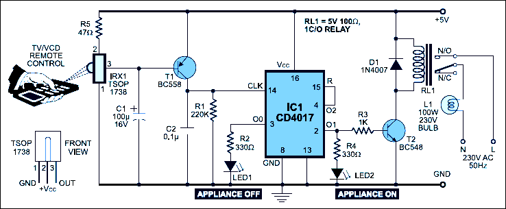 |
| Remote Control for Home Appliance Circuit Diagram |
Smart homes
Smart homes: the future of energy efficiency?
Imagine a future where your entire home and all your appliances are connected to the Internet. Simply by opening an app on your smartphone, you can adjust your air conditioning and turn off your lights. You can login to a single website where you can manage your home’s climate control, check how much power each appliance is consuming, and compare that to the amount of energy your rooftop solar array is generating. Not only would such a system be highly convenient, it would also enable homeowners to closely track and reduce their electric consumption.
 |
| Smart homes |

PID Controllers
PID Controllers
......................
 |
| Fig.PID Controllers |
PID controllers are named after the Proportional, Integral and
Derivative control modes they have. They are used in most automatic
process control applications in industry. PID controllers can be used to
regulate flow, temperature, pressure, level, and many other industrial
process variables. This blog reviews the design of PID controllers and
explains the P, I and D control modes used in them.
Li-Fi replace Wi-Fi in China
Li -Fi technology!!
Li-Fi to replace Wi-Fi in China
Li-Fi to replace Wi-Fi in China
 |
| Fig.1 Li-Fi to replace Wi-Fi in China |
Four computers can be connected to internet through one- watt LED bulb using light as a carrier instead of traditional radio frequencies, as in Wi-Fi, said Chi Nan, an information technology professor with Shanghai's Fudan University.
Chinese scientists have successfully developed a new cheaper way of getting connected to internet by using signals sent through light bulbs instead of radio frequencies as in 'Wi-Fi', a move expected to radically change process of online connectivity.
 |
| Fig.2 Li-Fi to replace Wi-Fi in China |
Inside Nuclear Power Plan
Inside Nuclear Power Plan
We will make it clear with pictures
 |
| Inside Nuclear Power Plan |
Compound Generators
Compound Generator
Series-wound and shunt-wound generators have a disadvantage in that
changes in load current cause changes in generator output voltage. Many
applications in which generators are used require a more stable output
voltage than can be supplied by a series-wound or shunt-wound generator.
One means of supplying a stable output voltage is by using a compound
generator.
The compound generator has a field winding in parallel with the
generator armature (the same as a shunt-wound generator) and a field
winding in series with the generator armature (the same as a series-wound generator) (Figure 1).
 |
| Figure 1 Compounded DC Generator |
The two windings of the compounded generator are made such that their magnetic fields will either aid or oppose one another.
If the two fields are wound so that their flux fields oppose one another, the generator is said to be differentially-compounded. Due to the nature of this type of generator, it is used only in special cases and will not be discussed further in this text.
If the two fields of a compound generator are wound so that their magnetic fields aid one another, the generator is said to be cumulatively-compounded.
As the load current increases, the current through the series field
winding increases, increasing the overall magnetic field strength and
causing an increase in the output voltage of the generator. With proper
design, the increase in the magnetic field strength of the series
winding will compensate for the decrease in shunt field strength.
Therefore, the overall strength of the combined magnetic fields remains
almost unchanged, so the output voltage will remain constant. In
reality, the two fields cannot be made so that their magnetic field
strengths compensate for each other completely. There will be some
change in output voltage from the no-load to full-load conditions.
In practical compounded generators, the change in output voltage from
no-load to full-load is less than 5 percent. A generator with this
characteristic is said to be flat-compounded (Figure 2).
 | |
| Figure 2 Voltage-vs-Current for a Compounded DC Generator |
For some applications, the series winding is wound so that it
overcompensates for a change in the shunt field. The output gradually
rises with increasing load current over the normal operating range of
the machine. This type of generator is called an over-compounded
generator. The series winding can also be wound so that it
under-compensates for the change in shunt field strength. The output
voltage decreases gradually with an increase in load current. This type
of generator is called an under-compounded generator.
Series-Wound DC Generators
Series-Wound DC Generators
When the field winding of a DC generator is connected in series with the
armature, the generator is called a series-wound generator (Figure 1).
The excitation current in a series-wound generator is the same as the
current the
generator delivers to the load. If the load has a high resistance and
only draws a small amount of current, the excitation current is also
small. Therefore,
the magnetic field of the series field winding is weak, making the
generated voltage low. Conversely, if the load draws a large current,
the excitation current is also high. Therefore, the magnetic field of
the series field winding is very strong, and the generated voltage is
high.
 |
| Figure1 Series-Wound DC Generator |
As you can see in Figure 2, in a series generator, changes in load
current drastically affect the generator output voltage. A series
generator has poor voltage regulation, and, as a result, series
generators are not used for
fluctuating loads. As is the case for the shunt-wound generator, a
series-wound generator also exhibits some losses due to the resistance
of the windings and
armature reaction. These losses cause a lower terminal voltage than that
for an ideal magnetization curve.
 |
| Figure 2 Output Voltage-vs-Load Current for Series-Wound DC Generator |
Shunt-Wound DC Generators
Shunt-Wound DC Generators
When the field winding of a generator is connected in parallel with the generator armature, the generator is called a shunt-wound generator (Figure 1).
 |
| Figure 1 Shunt-Wound DC Generator |
The excitation current in a shunt-wound generator is dependent upon the output
voltage and the field resistance. Normally, field excitation is maintained
between 0.5 and 5 percent of the total current output of the generator.
The shunt-wound generator, running at a constant speed under varying
load conditions, has a much more stable voltage output than does a
series-wound generator. Some change in output voltage does take place.
This change is caused by the fact that, as the load current increases,
the voltage drop (IaRa) across the armature coil
increases, causing output voltage to decrease. As a result, the current
through the field decreases, reducing the magnetic field and causing
voltage to decrease even more. If load current is much higher than the
design of the generator, the drop in output voltage is severe. For load
current within the design range of the generator, the drop in output
voltage is minimal (Figure2).
 |
| Figure 2 Output Voltage-vs-Load Current for Shunt-Wound DC Generator |
DC Generators Equipment Construction
DC Generators
DC Equipment Construction
Direct current machines are energy transfer devices. These machines can function as either a motor or a generator. DC motors and generators have the same basic construction, differing primarily in the energy conversion. To better understand the operation and construction of DC machines, a few basic terms must be understood.
Armature
The purpose of the armature is to provide the energy conversion in a DC machine (refer to Figure 1).
 | ||
| Figure 1 Basic DC Machine |
In a DC generator, the armature is rotated by an external mechanical
force, such as a steam turbine. This rotation induces a voltage and
current flow in the armature. Thus, the armature converts mechanical
energy to electrical
energy.
In a DC motor, the armature receives voltage from an outside
electrical source and converts electrical energy into mechanical energy
in the form of torque.
Rotor
The purpose of the rotor is to provide the rotating element in
a DC machine (refer to Figure 1). In a DC generator, the rotor is the
component that is rotated by an external force. In a DC motor, the rotor
is the component that turns a piece of equipment. In both types of DC
machines, the rotor is the armature.
STOTR
The stator is the part of a motor or generator that is
stationary (refer to Figure 1). In DC machines, the purpose of the
stator is to provide the magnetic field. The stator in Figure 1 is
provided by a permanent magnet.
Field
The purpose of the field in a DC machine is to provide a
magnetic field for producing either a voltage (generator) or a torque
(motor) (refer to Figure 1). The field in a DC machine is produced by
either a permanent magnet or an electromagnet. Normally, electromagnets
are used because they have an increased magnetic strength, and the
magnetic strength is more easily varied using external devices. In
Figure 2, the field is provided by the stator.
 |
| Figure 2 AC to DC Conversion with a Commutator |
EDDY CURRENTS
EDDY
CURRENTS
In the discussion on the previous
page you learned about electromagnetic induction. You
learned that anytime a conductor was placed in a changing magnetic
field that electrical current was generated in the conductor.
We talked about the conductor being a piece of wire that is often
wrapped into a coil, but the conductor does not need to be in
the shape of a coil and does not even need to be wire. It could
be a piece of flat steel, aluminum plate, or any other conductive
object. The only requirement is that the object must be able to
conduct electrical current.
When current is induced in a conductor
such as the square piece of metal shown above, the induced current
often flows in small circles that are strongest at the surface
and penetrate a short distance into the material. These current
flow patterns are thought to resemble eddies in a stream, which
are the tornado looking swirls of the water that we sometimes
see. Because of this presumed resemblance, the electrical currents
were named eddy currents.

Uses of eddy currents
Just like in our transformer experiment,
these induced eddy currents generate their own magnetic field.
After all, this is an actual electrical current and any current
flowing in a conductor produces a magnetic field, right? The detection
and measurements of the strength of the magnetic fields produced
by the eddy currents makes it possible for us to learn things
about conductive materials without even contacting them. For example,
the electrical conductivity of a material can be determined by
the strength of the eddy currents that form. Also since cracks
and other breaks in the surface of a material will prevent eddy
currents from forming in that region of the surface, eddy currents
can be used to detect cracks in materials. This is referred to
as eddy current testing in the field of nondestructive testing
(NDT). NDT technicians and engineers use eddy current testing
to find cracks and other flaws in part of airplanes and other
systems where bad things can happen if the part breaks. On the
next page you will learn more about eddy current testing and be
able to try an inspection yourself.
Subscribe to:
Posts (Atom)